| 001: A Full Life Cycle Systems Engineering and Software Development Environment Development Before The Fact In Action |
By Margaret H. Hamilton |
| Often, the only way to solve major issues or to survive
tough times is through non traditional paths or innovation. This can be accomplished by
creating new methods or new environments for using new methods. The answers for success
may well exist within our mistakes or problems. The first step is to recognize the true
root problems, which can then be categorized in terms of how to prevent them in the
future. This is followed by deriving practical solutions. The process is then repeated by
looking for new problem areas in terms of the new solution environment and repeating the
same problem-solving scenario. The development before the fact approach was derived from the combination of steps taken to solve the problems of traditional systems engineering and software development. What makes development before the fact different is that it is preventative instead of curative (see Inside Development Before the Fact, Electronic Design, April 4, 1994, p.8 ES). Consider such an approach in its application to a human system. To fill a tooth before it reaches the stage of a root canal is curative with respect to the cavity, but preventative with respect to the root canal. Preventing the cavity by proper diet is not only preventative with respect to the root canal but for the cavity as well. The scenario with the cavity followed by the root canal is the most expensive; the one with the cavity that was fixed on time is the next most expensive; and the one where there was no cavity is the least expensive. The act of being preventative is a relative concept. The idea is to prevent any thing that could go wrong in the life cycle that would later need to be fixed up after it was done incorrectly (or allowed to become incorrect due to negligence). For any given system, be it a human or software one, the goal is to be preventative to the greatest extent and as early as possible. Each development before the fact system is defined with properties that control its own design and development throughout its life cycle(s) where the life cycle, itself, is an evolving system that could be defined and developed as a target system using this approach. An emphasis is placed on defining things with the right methods the first time, formally preventing problems before they happen. Both function and object-oriented, it is based upon a unique concept of control. From the very beginning, a system inherently integrates all its own objects (and all aspects, relationships and viewpoints of these objects) and the combinations of functionality using these objects; maximizes its own reliability and flexibility to change (including reconfiguration in real time and the change of target requirements, static and dynamic architectures and processes); capitalizes on its own parallelism; supports its own run-time performance analysis; and maximizes the potential for its own reuse and automation. It is defined with built-in quality and built-in productivity. This is in contrast to traditional environments that support their users in fixing wrong things up or in performing tasks that should no longer be necessary instead of doing things right in the first place. As a result things happen too late if at all (i.e., after the fact). This article will discuss an automation of the development before the fact systems engineering and software development approach, which was described in the April 4 issue. This article also discusses practical experience in the design and development of systems using this approach. Development before the fact includes a language, a technology, and a process (or methodology), all of which are based upon a formal theory. |
| THE PROCESS |
| To review the process, the first step in building a
before the fact system is to manage the system by configuring the process management
environment. The next is to define a model. This model could be for any kind of
application. The model is automatically analyzed , statically and dynamically, to ensure
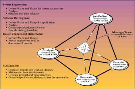
that it was defined properly. Management metrics are collected and analyzed. If the analysis process finds an error, control is returned to the definition process. If there are no errors, a fully production ready and fully integrated software implementation, consistent with the model, is then automatically generated by the generic generator for a selected target environment in the language and architecture of choice. If the selected environment has already been configured, that environment is selected directly; if not, the generator is configured for a new language and architecture before it is selected. The resulting system can then be executed. It becomes operational after testing. Target changes are made to the definition, not to the code. Target architecture changes are made to the configuration of the generator environment, not to the code. Once a system has been developed, the system and the process used to develop it are analyzed in order to understand how to improve the the next round of system development. The process is evolved before proceeding through another iteration of system engineering and software development. The key to development before the fact is the language. The definition space is a set of real world objects (Figure 1). Every model is defined in terms of functional maps (FMaps) to capture time characteristics and type maps (TMaps) to capture space characteristics. A map is both a control hierarchy and a network of interacting objects. Maps of functions are integrated with maps of types. FMaps and TMaps guide the designer in thinking through his concepts at all levels of system design. The execution space is the realization of FMaps and TMaps in terms of EMaps and OMaps. OMaps (representing objects) are instantiations of TMaps and EMaps (representing executions) are instantiations of FMaps. 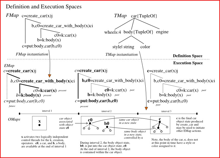 Figure 1: Definition/Execution Spaces of USL Defined Systems The duality of FMaps and TMaps is always present. Every type is associated with a node of a TMap, every function with a node of an FMap. Primitive types reside at the bottom nodes of a TMap; primitive functions (where each primitive function is a use of a primitive operation of a type in a TMap) are at the bottom of an FMap. Each type is defined in terms of its children types. All types are therefore ultimately defined in terms of primitive types. Each function is defined in terms of it children functions. All functions are therefore ultimately defined in terms of primitive functions. Each type has a set of primitive operations associated with it. A set of operations for a non-primitive data type is inherited from the particular parameterized type used to decompose the non primitive type into its children. A set of operations is included with each primitive type. A set of operations for a primitive type is implemented in terms of FMaps and TMaps (or it could be implemented in some other language such as the native language of the computer). Whereas an FMap uses types defined in terms of TMaps to define the behavior of its inputs and outputs, a TMap uses functions (defined in terms of FMaps) to define the behavior of its types. Properties of classical object-oriented systems such as inheritance, encapsulation, polymorphism and persistence are introduced with the use of TMaps. Special object-oriented operators can be created by the user as reusables with support from Type, OMap and Type, TMap. Type, OMap allows the user to treat any object as a generic object when it is desirable to do so such as finding out about the relationships of an object. Type, TMap allows the user to make queries about an objects type such as the context within which it is being used. For example, a wheel can determine if it belongs to a truck or a plane. Those building block definitions, which focus more on objects than on functions, are independent of particular object-oriented implementations. The 001 tool suite, an automation of development before the fact, is a full life cycle systems engineering and software development environment encompassing all phases of development. It begins with the definition of the meta process and the definition of requirements (Figure 2). From FMaps and TMaps any kind of system can be designed and any kind of software system can be automatically developed, resulting in complete, integrated, and fully production-ready target system code (or documentation) configured for the language and architecture of choice. The tool suite also has a means to observe the behavior of a system as it is being evolved and executed in terms of OMaps and EMaps. Every system developed with the tool suite is a development before the fact system. Since the tool suite was used to define and generate itself, it is a development before the fact system. Although the tool suite is a full life cycle design and development environment, it can coexist and interface with other tools. The tool suite can be used to prototype a system and/or to fully develop that system. A discussion of its major components follows.
Figure 2 |
| MANAGEMENT |
| The generalized manager, Manager(x), is that part of
the tool suite that allows users to tailor his own development environment. It is based on
the Virtual Sphere (VSphere) capabilities, also a part of the tool suite. VSphere supports
a layered system of interactive, user-definable, distributed hierarchical abstract
managers. Since the tool suite is a Manager(x) configuration, users can extend the tool
suite environment itself. For users, these extensions might be interfaces to other tools
their environment or tools that they design and develop with the tool suite to provide
automations to support their specific process needs. To tailor a manager, users define
their process needs with FMaps and TMaps and then install them into Manager(x). The Requirements Traceability (RT(x) ) tool, a subsystem within the tool suite that is also a Manager(x) configuration, provides users with more control over their own requirements process. RT(x) generates metrics and allows users to enter requirements into the system and trace between these requirements and corresponding FMaps and TMaps throughout system specification, detailed design, implementation and final documentation. The purpose of a manager is to coordinate user activities with objects on the abstract layer, which is appropriate for the users domain of interest. Each object being managed has a outside and an inside view. This allows a user to manage objects from an outside layer with a viewpoint that hides the internal details of the object being managed. For example, a user who is responsible for knowing that his requirements are satisfied may not need to know the details of the interconnections between requirements and the target system components that satisfy those requirements. |
| USING VSPHERE |
| With VSphere, Manager(x) can provide object relations
that are explicitly traceable. A user can define any relationship between objects and
describe the complex dependencies between these objects. This provides the user the
ability to query on those relationships. The relationships between a set of requirements
and its supporting implementation is an example. Although VSphere supports Manager(x) in
providing a user callable and distributable object management system layer, a user can
directly use VSphere as a data type from within his applications to provide control and
distribution of his objects. This also allows the users application to behave as an object
manager for users of that users application. A default set of general-purpose interactive management functions with a default interactive graphical representation is available with Manager(x). Graphical methods are used for representing and entering information. Users can override default functions with their own tailor made functions or extensions to the defaults provided. By default, a development before the fact process model is supported with the tool suite (e.g., evolve, define, analyze, resource allocate, execute). A managers basic functions include: 1) extension: a user may extend the life cycle development process object types, which may be managed and their associated primitive operations, which a manager may control. These extended object types are defined in terms of other object types; 2) evolution by abstraction: a user may import an existing representation into the definition language form; 3) definition: a user may create, delete, and modify object instances of these user extended object types; 4) analysis: a user may define analysis functions that result in status changes to objects (i.e., consistency and completeness); 5) resource allocation: a user may define transformation functions to generate other forms of information in terms of a resource about the system of objects. Such transformations may include generation of code, English or management metrics; 6) execution: the user may run and test executable systems from within a managers environment and 7) general support: a user has a general purpose set of interactive functions (e.g., searching, navigation, schedule notification or event notification). The requirements for ideal systems engineering and software development are defined as part of the development before the fact paradigm. The tool suite with Manager (x) provides the user the capability and flexibility to fulfill these requirements with alternative specifications. The tool suite configuration of Manager(x) is provided as a default to its users. With this configuration the tool suite includes besides Manager(x), itself, the Session Manager for managing all sessions, the Project Manager for managing all projects, the Library Manager for managing libraries within one project, and the Definition Manager for managing definitions within a library. The Definition Editor of the Definition Manager is used to define FMaps and TMaps in either graphical or in textual form. Each manager manages a Road Map (RMap) of objects, including other managers, to be managed (Figure 3). An RMap provides an index or table of contents to the users system of definitions and supports the managers in the management of these definitions, including those for FMaps, TMaps, defined structures, primitive data types, objects brought in from other environments as well as other RMaps. Managers use the RMap to coordinate multi-user access to the definitions of the system being developed. Each RMap in a system is an OMap of the objects in the system used to develop that system within each particular managers domain. The Road Map Editor is used to define RMap hierarchies. 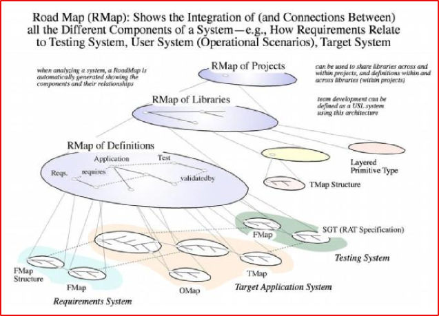
Definitions are submitted to the Structure Flow Calculator to automatically provide the structures and an analysis of the local data flow for a given model. At any point during the definition of a model, it may be submitted to the Analyzer, which ensures that the rules for using the definition mechanisms are followed correctly. |
| GENERATION |
| When a model has been decomposed to the level of
objects designated as primitive and successfully analyzed, it can be handed to the
Resource Allocation Tool (RAT), which automatically generates source code from that model.
The RAT is generic in that it can be configured to interface with language, database,
graphics, client server, legacy code, operating system, and machine environments of
choice. The Type RAT generates object type templates for a particular application domain
from a TMap(s). The code generated by the Functional RAT is automatically connected to the code generated from the TMap and code for the primitive types in the core library, as well as, if desired, libraries developed from other environments (because of the tool suites open architecture it can be configured by the user to generate code to interface with outside environments). To maintain traceability, the source code generated by the RAT has the same name as the FMaps and TMaps from which it was generated. The generated code can be compiled and executed on the machine where the tool suite resides (the tool suite currently resides on the HP 700 series, IBM RS 6000, SunOS 4.X/Solaris, and Digital Alpha UNIX, X Window, Motif, C and Ada environments); or, it can be ported to other machines for subsequent compilation and execution. User-tailored documents and metrics, with selectable portions of a system definition, implementation, description and projections (e.g., parallel patterns, decision trees and priority maps) can also be configured to be automatically generated by the RAT. Once a system has been RATted, it is ready to be compiled, linked and executed. The RAT provides some automatic debugging in that it generates test code, which finds an additional set of errors dynamically (e.g., it would not allow one to put an engine into a truck if it already had one or try to take an engine out of a truck if it had no engine). The developer is notified of the impact in his system of any changes and those areas that are affected (e.g, all FMaps that are affected by a change to a TMap) are demoted. |
| CONTROLLED VISUALIZATION |
| The next step is to execute/test the system. One tool
to use in this step is Datafacer, a run-time system that automatically generates a user
interface based on the data description in the TMap. In the development of systems,
Datafacer can be used in two major ways: as a general object viewer and editor and as a
full end-user interface. The tool suite automatically generates a unit test harness
incorporating Datafacer as a default test data set and data entry facility for subsystem
functions being developed. Datafacer chooses appropriate default visualizations for each
data item to be displayed. For a specific OMap, it manages the visualization of specific
data values for the user and the modification of the OMap by the user with its OMap
Editor. The TMap is the repository for information about the structure of data and it implies the operations that may be performed on it. The visualization of data created from the TMap consists of interface elements that display the values in the OMap and interface elements that trigger primitive functions on those values. For example, an ordered set might be depicted as a list, with buttons for insert and extract; a boolean might be visualized as a toggle switch. For each primitive and parameterized type, there are a group of modes of visualization from which to choose. For example, a number can be visualized as a text item with the number in it or a dial that can be turned to the desired value. In addition, advanced users can add new ones. Datafacer produces forms-entry screens, much like conventional database screen painters, but supports the full semantic capabilities of TMap. It will generate screens for arbitrary depth type hierarchies and has full support for parameterized types OrderedSetOf, TreeOf, OneOf and TupleOf. The developer has control over the data that may be viewed or modified by the user. Data in the OMap may be reorganized, specified as view-only or completely hidden from the user. Using data type DFACE (the API to Datafacer functions) the developer has complete control over visualization and data modification from within his application. Here, the developer can add functions to capture run-time data events (like trigger functions), perform constraint checking, data analysis and specialized graphics manipulations. Besides data specification, the developer has access to many graphical configuration options. Some of these may be carefully controlled while others may be left for users to change. A common capability allows end users to save the locations and sizes of their windows between sessions. Datafacer focuses on several basic principles: Many applications center around the display and modification of data; the visualization of data structures may be generated and managed automatically by understanding the semantics of the data description; the automation is made useful by a wide array of configuration avenues, for both the developer and end user; and the system may be configured in many ways. A set of reasonable defaults is always provided that allows rapid prototyping and gives the developer a concrete starting point. |
| SIMULATION |
| The Xecutor executes directly the FMaps and TMaps of a
system by operating as a runtime executive, as an emulator or as a simulation executive.
As an executive, the Xecutor schedules and allocates resources to activate primitive
operations. As an emulator of an operating system, the Xecutor dispatches dynamically
bound executable functions at appropriate places in the specification. As a simulator, the
Xecutor records and displays information. It understands the real-time semantics embedded
in a 001 definition by executing or simulating a system before implementation to observe
characteristics such as timing, cost, and risk based upon a particular allocation of
resources. If the model being simulated by the Xecutor has been designed to be a
production software system, then the same FMaps and TMaps can be RATted for production.
The Xecutor can be used to analyze processes such as those in a business (enterprise
model), manufacturing or software development environment (process model) as well as
detailed algorithms (e.g., searching for parallelism). The Baseliner facility provides version control and base lining for all RMaps, FMaps, TMaps and user defined reusables, including defined structures. The Build Manager Configuration Control facility's primary role is to manage all entities which are used in the construction of an executable. This includes source files, header files and context information about the steps taken to produce the executable. This facility also provides options for controlling the optimization level, debugging information, and profiling information of the compiled code. |
| EXAMPLE DEVELOPMENT SCENARIOS |
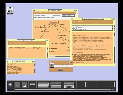
| Figures 4, 5, 6 and 7 show excerpts of a development
scenario starting with the definition of requirements in the form of a users English
document from which key expressions (e.g., fire fighting system) and key words (e.g.,
shall) are filtered (Figure 4). Those statements with the key words and expressions can
then be attached to the RMap along with information of the users choice for the purpose of
establishing traceability and gathering metrics throughout the life cycle. Reusables can
be used to fulfill some of the requirements associated with the nodes on the RMap. For
others, some FMaps and TMaps may already have been defined for this system. Others are yet
to be defined.
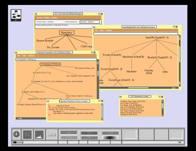
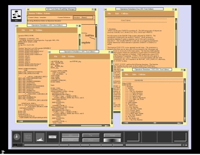
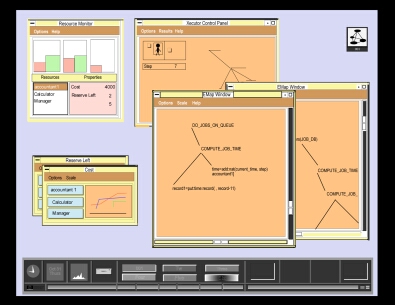
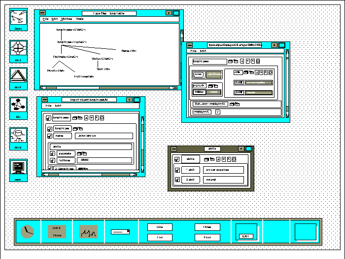
The next step is to define and analyze FMaps and TMaps (Figure 5), continuing with the automatic generation of production ready code for C and Ada and the generation of English (Figure 6). This is followed by a session with the CPU run time environment for testing and deployment or the Xecutor which shows the system being executed by running the FMaps (resulting in EMaps) and TMaps (resulting in OMaps) along with the resources being used by them (Figure 7). In another session (Figure 8), Datafacer is being used to edit an OMap (lower left) based upon TMap, Employees (upper left). An alternative Datafacer visualization of the OMap being edited, configured by the user, is also shown (upper right). With the RT(x) manager, user requirements in any form can be entered into the 001 environment, providing user configurable life cycle management, requirements traceability and metrics gathering. These requirements are attached to the target systems Road Map which is used to manage the system. The Definition Editor is used to create FMaps and TMaps to define the system. The system is analyzed with the Analyzer. Integrated, complete and fully production ready code for any kind of system can be generated by the RAT. The RAT, currently configured to generate C, Ada and English, can be configured to generate to any architecture including any language, graphics, OS, database, communications protocol and legacy code. The Xecutor runs the FMaps and TMaps in the form of EMaps (instantiations of FMaps) and OMaps (instantiations of TMaps). With the Xecutor simulator, the behavior and performance of a system can be analyzed. Datafacer can be used as an object viewer, object editor or as a full, end-user interface. It produces forms-entry screens which can be configured by the user. It automatically generates a user interface supporting the semantic capabilities of TMap. With the use of the tool suite, a development process is automated within each phase and between phases beginning when the user first inputs his thoughts and ending when testing his ideas. The same language and the same tools can be used throughout all phases, levels and layers of design and development. There are no other languages or tools to learn. Each development phase is implementation independent. A system can be automatically RATted to various alternative implementations without changing its original definition. Traceability is backwards and forwards from the beginning of the life cycle to implementation to operation and back again (for example, the generated code has names corresponding to the original requirements). Traceability also exists upwards and downwards since requirements to specification to design to detailed design is a seamless process. A primitive in one phase (e.g., requirements) becomes the top node for a module in the next lower level phase (e.g., specifications). The tool suite takes advantage of the fact that a system is defined from the very beginning to inherently maximize the potential for its own automation.
Figure 4
Figure 5
Figure 6
Figure 7
Figure 8 |
| RESULTS |
| Many systems have been designed and developed with this
paradigm. Some of these systems were from the systems engineering domain and some were
from the software development domain; others were a combination of both. The definition of
these systems began either with the process of defining the original requirements or with
requirements provided by others in various forms. The process varied from one extreme of
interviewing the end user to obtain the requirements to the other of receiving written
requirements. These systems include those that reside within manufacturing, aerospace,
software tool development, transaction processing, process control, simulation,
communications, domain analysis, and database management environments.
One system developed with 001 is the 001 tool suite itself. Approximately 800,000 lines of code were automatically generated for each of four platforms by the tool suite to create itself. The tool suite generated itself in C for its production version. It has generated portions of itself in Ada for purposes of testing aspects of Ada. Over 7 Million lines of code have been generated by the tool suite to generate all of its 3 major versions on these platforms. Contained within the tool suite are many kinds of applications, including database management, communications, client server, graphics, software development tools, and scientific applications. All of the tools within the tool suite are inherently integrated as part of the same system. The OpenINGRES Object Generator, a database management system, is an example of a system developed with 001 that has parts of the 001 tool suite embedded within it, including portions of Datafacer. It is an interactive tool for application developers who need to implement encapsulated objects as new data types within the OpenINGRES database. Recently, the tool suite was part of an experiment sponsored by the National Test Bed (NTB). The NTB provided the same problem to each of three contractor/vendor teams. The application was real time, distributed, multi-user, client server, and was required to be defined and developed under government 2167A guidelines. All teams successfully completed the definition of preliminary requirements, two teams continued on to successfully complete detailed design and one team, the 001 team continued on to automatically generate complete and fully production ready code; a major portion of this code (both C and Ada were generated from the same definitions) was running in both languages at the completion of the experiment. |
| ANALYSIS |
| We have analyzed our results on an ongoing basis to
understand more fully the impact that properties of a systems definition have on the
productivity in its development. Productivity was analyzed with several systems and then
documented. Compared to a traditional C development where each developer produces 10 lines
of code a day, the productivity of the 001 developed systems varied from 10 to 1 to 100 to
1. Upon further analysis, unlike with traditional systems, the larger and more complex a
system, the higher the productivity. This is in major part because of the high degree of
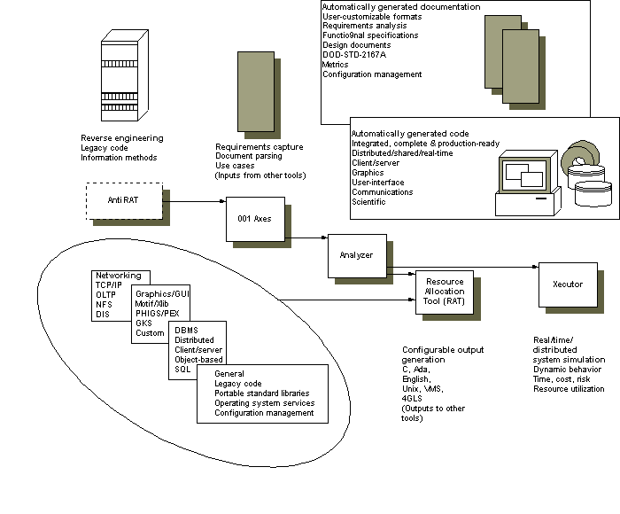
reuse on larger systems. Figure 9 shows the development before the fact systems engineering and software development environment with a focus on its open architecture aspects. This environment provides a new set of alternatives for disciplines associated with the traditional development process. Take for example, reverse engineering. Redevelopment is a more viable option, since a system can be developed with higher reliability and productivity than before. Another alternative is to develop main portions of the system with this approach but hook into existing libraries at the core primitive level and reuse portions of existing legacy code that are worth reusing, at least to get started. In the future, however, for those systems originally developed with the tool suite, reverse engineering becomes a matter of selecting the appropriate RAT configuration or of configuring the RAT environment of choice and then RATting to the new environment.
Figure 9 The tool suite has evolved over the years based upon user feedback and a continuing direction of capitalizing more on advanced capabilities of development before the fact. Datafacer and DFACE are examples of newer tools to be made recently available to external users. This was after the developers of the tool suite used it for several months to develop the most recent versions of the tool suite. Manager(x), an even newer capability, is similarly evolving with the developers of the tool suite. Once completed, new components to be added to the tool suite environment are the generic Anti-RAT and the architecture independent operating system (AIOS). The Anti-RAT performs the reverse function of the RAT. Anti-RATting is an evolution process step where one language representation is transformed into another language representation. With the anti-RAT legacy code and definitions can be reverse engineered to FMaps and TMaps and become a development before the fact system before proceeding through the RAT process to generate (regenerate) the target system in the language of choice. The amount of user interaction after the FMaps and TMaps have been generated depends on how formal the legacy code was in the first place. It will also depend on the degree to which the user would like to change or raise the level of his specification (e.g, instead of anti-RATting from FORTRAN to FMaps and TMaps and then directly RATting to AdaTRAN, the user may wish to anti-RAT to FMaps and TMaps and then raise the level of the specification before RATting to Ada. There are advantages and disadvantages to all of these reverse engineering approaches depending on the particular requirements and constraints of the user. The Tool Suite currently has an instance of the Anti-RAT in that it can generate FMaps and TMaps from equations. The can attach equations to the bottom nodes of FMaps and make use of this capability. The AIOS will have the intelligence to understand the semantics of functional, resource and resource allocation architectures since all of these architectures can be defined in terms of FMaps and TMaps. It will make use of the information in their definitions (including the matching of independencies and dependencies between architectures) to automatically determine sets of possible effective matches between functional and resource architectures. The Distributed Xecutor, a module of the AIOS, will provide for real time distributed object management capabilities where the users application will be fully transparent to client server programming techniques and communication protocols. Insert Figure 9. The 001 tool suite is a seamless and open architecture environment. It inherently supports an integration of function and object oriented development. |
| THE PARADIGM SHIFT |
| It becomes clear that when critical issues are dealt
with after the fact, a systems quality and productivity in producing it are compromised
beyond belief. True reuse is ignored. System integrity is reduced at best. Functionality
is compromised. Responding to today's rapidly changing market is not practical. Deadlines
are missed, time and dollars wasted. The competitive edge is lost. Collective experience
strongly confirms that quality and productivity increase with the increased use of
development before the fact properties. A major factor is the inherent reuse in these
systems culminating in ultimate reuse which is automation, itself.
With development before the fact, all aspects of system design and development are integrated with one systems language and its associated automation. With the tool suite, systems engineering and software development are merged into one discipline. Systems are constructed in a tinker toy-like fashion. Reuse naturally takes place throughout the life cycle. Functions and types, no matter how complex, can be reused in terms of FMaps and TMaps and their integration. Objects can be reused as OMaps. Scenarios can be reused as EMaps. Environment configurations for different kinds of architectures can be reused as RAT environments. A newly developed system can be safely reused to increase even further the productivity of the systems developed with it. The paradigm shift occurs once a designer realizes that many of the things that he used before are no longer needed to design and develop a system. For example, with one formal semantic language to define and integrate all aspects of a system, diverse modeling languages (and methodologies for using them), each of which defines only part of a system, are no longer a necessary part of the process. There is no longer a need to reconcile multiple techniques with semantics that interfere with each other. Techniques for bridging the gap from one phase of the life cycle to another become obsolete. Techniques for supporting the manual process rather than replacing it such as that of maintaining source code as a separate process are no longer needed since the source is automatically generated (and regenerated) from the requirements specification. Verification (the process of verifying that a particular code implementation matches the requirements) becomes an obsolete process as well. Techniques for managing paper documents can be replaced by entering requirements and their changes directly into the requirements specification data base that supports the requirements, such as generating documentation from them. Clear and accurate documentation will be able to support reuse at the layer of human understanding. Testing procedures and tools for finding the majority of errors are no longer needed because those errors no longer exist. The majority of tools developed to support programming as a manual process are no longer needed. It may be tempting at first when using a new paradigm to want to fall back into old habits such as using an informal method to define a part of a system. Such a method may provide an easier means of defining, for example, the recursive or the parallel parts of that aspect of the system. But does it really define it? And is it, then, really easier? Certainly not from the life cycle point of view. In the end, the right combination of methodology and the technology that executes that methodology forms the foundation of successful software. Software is so ingrained in our society that its success or failure changes dramatically the way businesses, including the agencies within our own government, are operated as well as their overall success. This is why the impact of decisions made today about systems engineering and software development will be felt well into the next century. |
| REFERENCES |
|
M. Hamilton, "Zero-Defect Software: the Elusive Goal," IEEE Spectrum, vol. 23, no. 3, pp., 48-53, March, 1986. M. Hamilton and R.Hackler, 001: A Rapid Development Approach for Rapid Prototyping Based on a System that Supports its Own Life Cycle, IEEE Proceedings, First InternationalWorkshop on Rapid System Prototyping, Research Triangle Park, NC, June 4, 1990. B. McCauley, Software Development Tools in the 1990s, AIS Security Technology for Space Operations Conference, July 1993, Houston, Texas. The 001 Tool Suite Reference Manual, Version 3. Cambridge, MA, Hamilton Technologies, Inc., January 1993. B. Krut, Jr., Integrating 001 Tool Support in the Feature-Oriented Domain Analysis Methodology (CMU/SEI-93-TR-11, ESC-TR-93-188), Pittsburgh, PA:Software Engineering Institute, Carnegie Mellon University, 1993. Software Engineering Tools Experiment-Final Report, Vols. 1, Experiment Summary, Table 1, p. 9, Department of Defense, Strategic Defense Initiative, Washington, D.C., 20301-7100. The OpenINGRES Object Generator reference manual, Version 1, Alameda, CA, ASK Group INGRES, June 1994. |
